Aircraft Vacuum System - This story was prepared in cooperation with Republic Airlines. Watch the full episode here. Are you ready to apply for a pilot position? Submit your application here.
No matter what you fly, your attitude indicator is one of your most important tools. But how exactly does it work?
Aircraft Vacuum System

A typical circular dial attitude indicator has an internal gyroscope that is rotated by your aircraft's vacuum system. Air is drawn from the winged rotor of the attitude indicator, causing the gyroscope to rotate.
Spl 1942 Plugs
It is a gyroscope that rotates in place, mounted horizontally on the attitude indicator housing. Attached to the arms of the gyroscope is a map with lines showing degrees of tilt and degrees of elevation outside.
The easiest way to think about how your flight attitude is determined is to imagine your airplane moving around a gyroscope, not a gyroscope.
A traditional attitude indicator measures the pitch and altitude of your aircraft based on the principle of rigidity in space. The gyroscope will remain in the same position until rotated (and there is no sudden change in attitude).
Newer solid-state avionics do not have the rotating parts used in circular dial position indicators. Instead, there is a version of AHARS or ADAHRS. AHARS stands for Attitude, Heading Reference System and ADAHRS stands for Weather Information Attitude Reference System.
Types Of Vacuum Cleaners
On some aircraft you will find AHRS and ADC, while others may have a combination of ADAHRS. Check Avionic's Pilot's Guide to see what your aircraft has.
For this explanation we will use the G1000 NXi installed on the PA28-181 aircraft. There may be slight differences between your aircraft and this example, but the principles will likely be the same.
The G1000 NXi system consists of LRUs (Line Replaceable Units). Think of them as the building blocks of a system. Each box is an LRU.

The ADAHRS unit transmits your flight data to the integrated avionics units as well as the flight displays. You will also notice that each LRU has multiple links. This is done to get fired.
Aero Safe Standby Vacuum System W/ Airborne Dry Air Pump (12v)
Your aircraft's attitude is calculated using two solid state gyroscopes. One is installed vertically and the other horizontally. The accelerometers on the GSU 75 unit, along with the magnetometer, help filter out small vibrations and shocks to keep your attitude indicator movements looking smooth.
But how do solid-state gyroscopes calculate your attitude information? The answer lies in a quarter-sized component called a microelectromechanical system, or MEMS for short.
MEMS gyroscopes have a vibrating element that can determine attitude based on Coriolis acceleration energy transfer. (AMT-Body Volume II 10-56)
Simply put, the vibrating element in the MEMS unit acts as a gyroscope and provides attitude information based on changes in vibration frequency.
Artificial Horzizon Inop On Multiple Aircraft
Older glass instruments may have a laser ring gyroscope (LRG). These systems use the Sagnac effect to determine pitch and bank data.
The Sagnac Effect is the principle that light takes longer to travel around an object rotating in the same direction as the light, and less time traveling in the opposite direction.
As the aircraft attitude changes, the LRG rotates and the wavelength of the laser light is changed, allowing the AHRS unit to process the attitude change. An LRG unit is required for each flight axis.
If you fly in a round number system, your attitude indicator uses a rotating gyroscope and the principle of stiffness in space to display your attitude information.
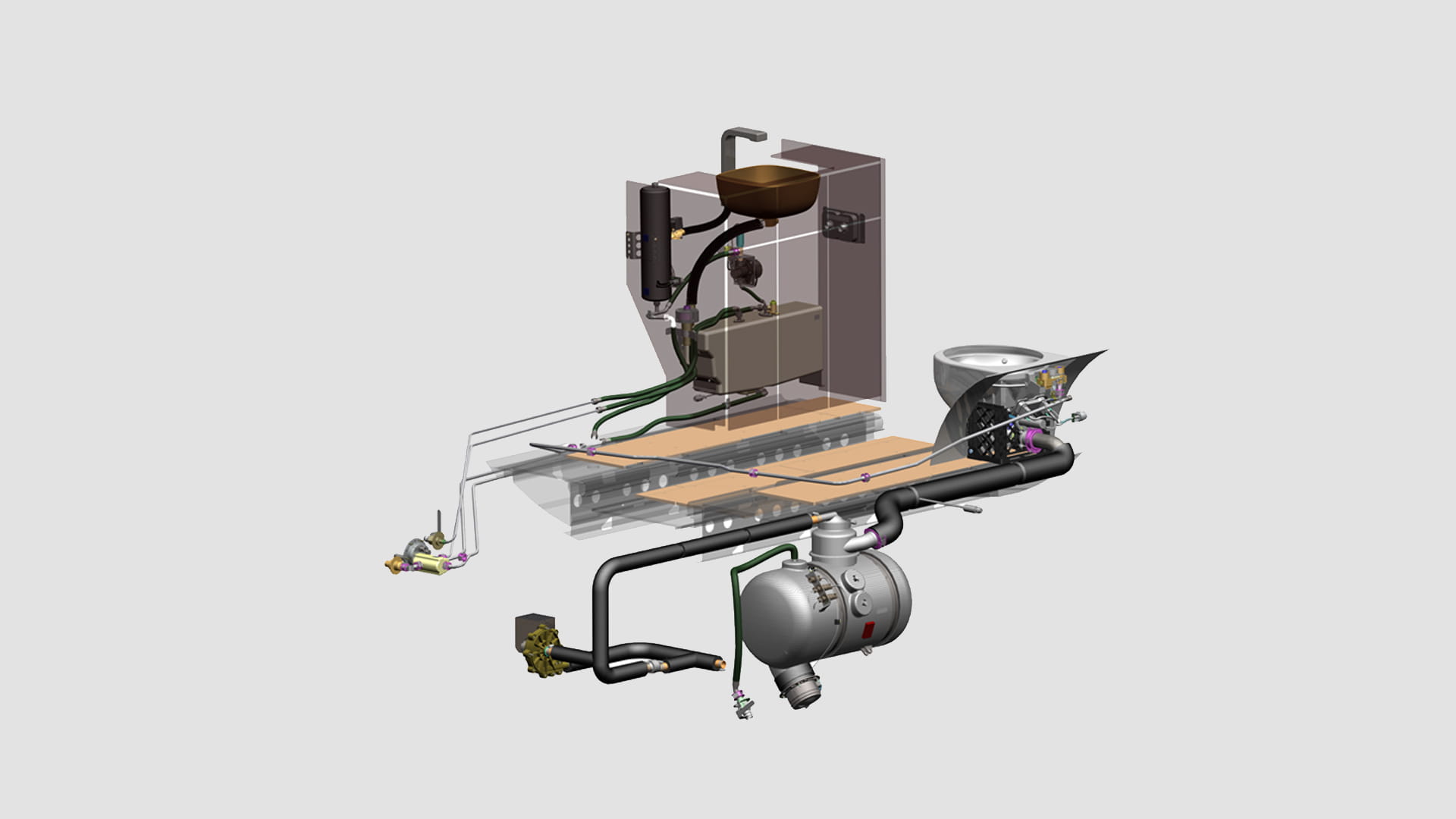
Vacuum Waste System
If you fly a modern glass cockpit airplane, your attitude information is calculated from solid-state accelerometers, often with the aid of a magnetometer.
Finally, if you are flying a transport class aircraft, your attitude information can be calculated using a laser ring gyroscope.
Ready to start your airline career? Want to fly the E-170/175? Get started and apply to Republic Airlines today.
Subscribe to the email and get real flight tips and information delivered straight to your inbox every week.
Announcement: G5 Electronic Flight Instrument Introduced As Dg/hsi For Certificated Aircraft
Nicholas is a flight instructor from Southern California. He is currently studying aviation at Purdue University. He worked on projects related to aviation safety and marketing. You can contact him at nicolas@ Gyro instruments are essential instruments used in all aircraft. They provide critical attitude and directional information to the pilot and are especially important when flying under IFR. The power sources of these devices may be different. The main requirement is to rotate the gyroscopes at high speed. At first, gyroscopic instruments operated strictly with vacuum. A vacuum source drew air from the gyroscope inside the instruments to spin the gyroscope. Later, electricity was added as a power source. The armature of the electric motor acts as the rotor of the gyroscope. Some aircraft use pressure instead of vacuum to control the gyro. Various systems and power configurations have been developed to ensure safe operation of gyroscopic instruments.
Vacuum Systems Vacuum systems are very common for driving gyroscope instruments. In a vacuum system, the air flow directed against the rotor blades rotates the rotor at high speed. The movement is similar to a water wheel. Air at atmospheric pressure is first drawn through the filter(s). It is then fed to the instrument and directed to the rotor blades of the gyroscope. A suction line leads from the body of the instrument to the vacuum source. From there, the air is discharged into the ship. Either a venturi tube or a vacuum pump can be used to provide the vacuum required to spin the rotors of the gyroscope instruments.
The vacuum required to operate the instrument is generally between 3½ inches and 4½ inches of mercury. This is usually regulated by a vacuum relief valve located in the supply line. Some turn and turn indicators require a lower vacuum intake. This can be achieved by using an additional control valve in the return and bank vacuum supply line.

Venturi Tube Systems The velocity of air through a venturi tube can create enough suction to spin instrument gyroscopes. A line is drawn from the gyro instruments to the throat of a venturi tube mounted on the outside of the airframe. The low pressure in the venturi pulls air through the instruments, spins the gyro, and pushes the air out of the venturi. This gyro power source was used in many simple, early aircraft.
Buy Vacuum And Compressed Air Systems Online
A light, single-engine aircraft can be equipped with a 2-inch venturi (vacuum capacity 2 inches of mercury) to control yaw and yaw. It may also have a larger 8-inch venturi to boost attitude and directional indicators. Simplified images of these venturi vacuum systems are shown in Figure 1. Normally, the air entering the instruments is filtered.
The advantages of the venturi as a suction source are its relatively low cost and ease of installation and operation. It also requires no electricity. But there are serious limitations. The venturi is designed to create the desired vacuum at about 100 mph above standard sea level. Wide variations in air speed or density cause variations in suction. Air flow can also be obstructed by ice that can build up in the venturi tube. Additionally, since the rotor does not reach normal operating speed until takeoff, pre-flight performance checks of venturi-powered gyros cannot be performed. For these reasons, alternative sources of vacuum energy were developed.
Engine-Driven Vacuum Pump The vane-type engine-driven pump is the most common source of vacuum for gyroscopes installed in general aviation and light aircraft. One type of engine driven pump is fitted to the engine and connected to the lubrication system to seal, cool and lubricate the pump. Another commonly used pump is the dry vacuum pump. It works without external lubrication and does not require connection to the engine oil supply for installation. It also does not require an air-oil separator or gate check valve found in wet pump systems. In many other ways, a dry pump system and an oil-lubricated system are the same. [2. picture]
When a vacuum pump creates a vacuum (negative pressure), it also creates a positive pressure at the outlet of the pump. This pressure is compressed air. It is sometimes used to power pressure gyro instruments. The components of a pressure system are basically the same as the components of a vacuum system, as follows. Other times, the pressure created by the vacuum pump is used to inflate or vent anti-ice boots or inflated seals.
Pdf] Comparative Vacuum Monitoring (cvm) Monitoring Of Fatigue Cracking In Aircraft Structures
The advantage of motor-driven pumps is that they operate continuously on the ground and in flight. Even at low engine rpm, they can produce quite a lot of vacuum, so a regulator is needed in the system to ensure proper vacuum tool suction at all times. While the motor is running, a relatively simple vacuum system rotates the instrument's gyroscope accordingly to obtain accurate readings. However, engine failure, especially in single-engine aircraft, can leave the pilot without attitude and directional information at a critical moment. To overcome this drawback, the yaw and roll indicator is often powered by an electrically powered gyroscope that can be powered by a battery for short periods of time. So when combined with the aircraft's magnetic compass, it is sufficient
Aircraft vacuum system diagram, aircraft vacuum reviews, vacuum instruments aircraft, aircraft vacuum cleaners, vacuum toilet system aircraft, aircraft vacuum gauge, vacuum cleaner for aircraft cleaning, aircraft vacuum, aircraft vacuum cleaner, aircraft vacuum pump application chart, aircraft vacuum pump, aircraft vacuum pumps

0 Comments